3-phase Induction Motor Efficiency and other issues?
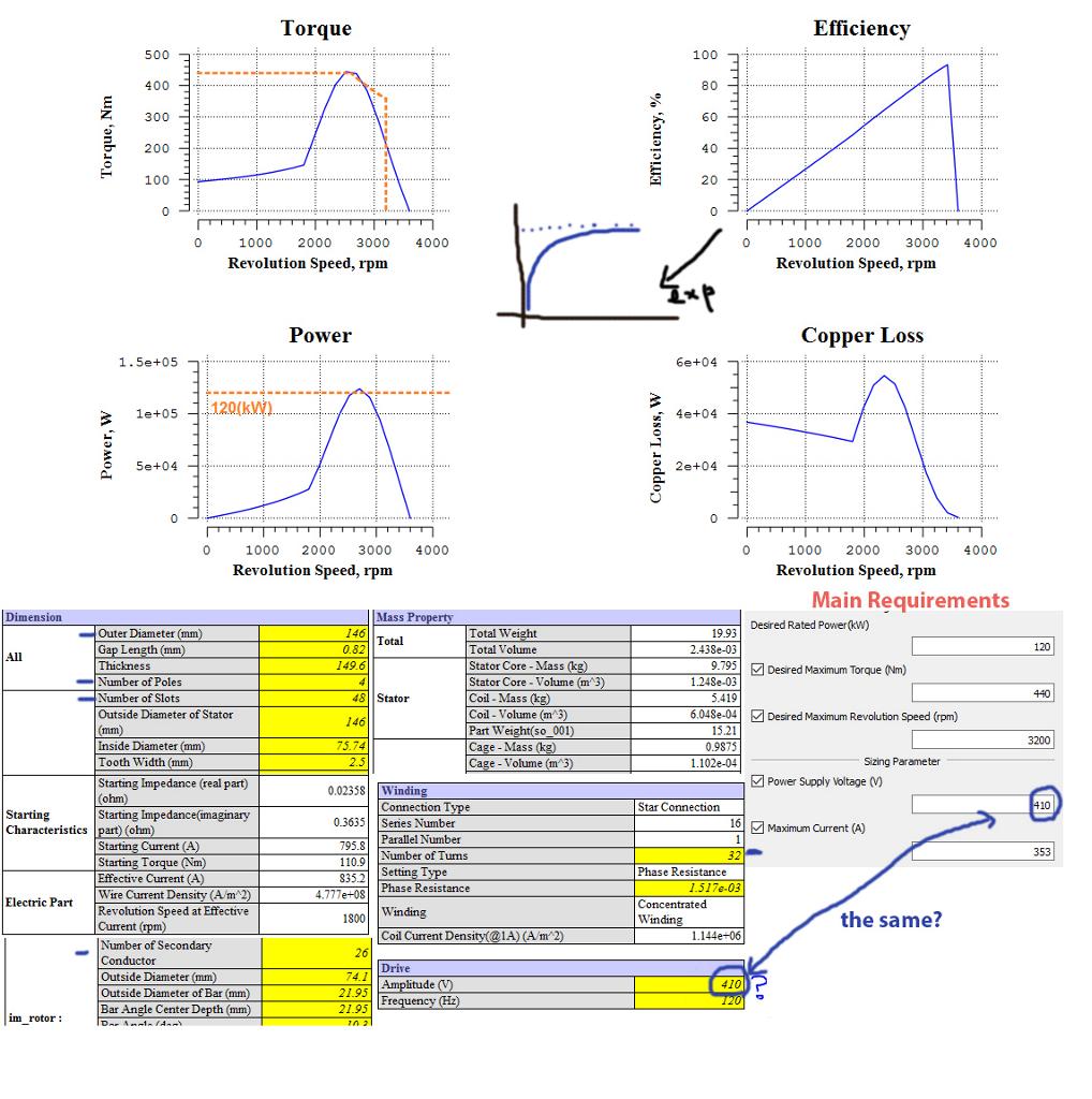
I'm in a motor design. Currently, I'm using JMAG Express to estimate the right sizing requirements for a 3-phase Induction Motor that I want to build among friends. As you can see from the picture, I need to be able to reach 3200 RPMs speed, 440 N*m torque and 120kW of max power. I've played around with some of the values in JMAG to reach a weight of around 20kg as you can see from the picture. The low weight is a very important requirement for the project and it should not exceed 50kg. I'm using 48 slots for the stator and 26 for the rotor which is a Caged type. Winding is concentrated with 32 turns.

One of the problems I'm seeing is in the Speed vs Efficiency curve. If I understand correctly, this should be more of an exponential curve like the one I have drawn, and not a linear one like I'm getting from the software. Why I am getting these results?
My second question is regarding the Drive requirements vs Main Requirements Voltage. In the main requirements I specify 410V as the Power Supply Voltage and under Drive I'm setting 410V for the Amplitude. Assuming that the PS Voltage is the DC Voltage that drives the inverter which in turns converts this into AC, is the Amplitude the value from one of the phases of the AC output of the inverter (which would be one of the inputs into the motor phases)? If so, what value should I be using instead of the 410V and what is the equation to get this value? If not, are both values the same thing?
My last and third question is regarding the winding parameters. JMAG just gives you the option of changing the Turns which I have set to 32 and the Phase Resistance. However, I don't understand how to determine the right gauge for the actual wires from these results and JMAG doesn't seem to give you this number or any kind of wire dimension. How can I determine this?
I'm open to any suggestions and appreciate any feedback or resource that you may provide. Thanks!
<- - Make a Comment - ->

 Servo Motor & Drives

