FAQ
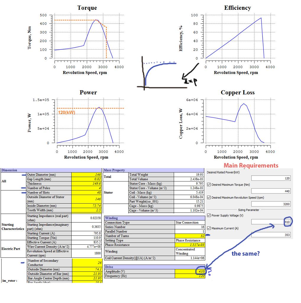
I'm in a motor design. Currently, I'm using JMAG Express to estimate the right sizing requirements for a 3-phase Induction Motor that I want to build among friends. As you can see from the picture, I need to be able to reach 3200 RPMs speed, 440 N*m torque and 120kW of max power. I've played around with some of the values in JMAG to reach a weight of around 20kg as you can see from the picture. The low weight is a very important requirement for the project and it should not exceed 50kg. I'm using 48 slots for the stator and 26 for the rotor which is a Caged type. Winding is concentrated with 32 turns.

Assuming that you checked the mechanical properties and the centrifugal force at the rotor at the higher speed from 50Hz to 60Hz,  and they are OK, then you have to consider that the flux in the machine will go down by the ratio of the increase of frequency to 60Hz. Also the inductances will increase, so locked amps will be down, Locked rotor torque will be down, power factor will change, and efficiency will change. No load amps will decrease. If you want to change the electrical design to make it like it was for 50Hz then you have to increase the number of turns of the motor, but you have to know what you are doing.
Please note that except the change in the asynchronous speed of the motor machine, many other parameters will change. This will include the effective phase impedance of the motor, the current/voltage levels, etc. Also, please note that the torque-speed curve and the associated efficiencies will be affected by the change in frequency 60Hz to 50Hz.
 and they are OK, then you have to consider that the flux in the machine will go down by the ratio of the increase of frequency to 60Hz. Also the inductances will increase, so locked amps will be down, Locked rotor torque will be down, power factor will change, and efficiency will change. No load amps will decrease. If you want to change the electrical design to make it like it was for 50Hz then you have to increase the number of turns of the motor, but you have to know what you are doing.
Please note that except the change in the asynchronous speed of the motor machine, many other parameters will change. This will include the effective phase impedance of the motor, the current/voltage levels, etc. Also, please note that the torque-speed curve and the associated efficiencies will be affected by the change in frequency 60Hz to 50Hz.
In general, the most common failure mode (>> 50%) of low voltage induction motors is bearing failure. Assuming that no special circumstances apply, i.e. no mission critical system, I would recommend to limit preemptive maintenance to vibration monitoring. This can either be done by using accelerometers, i.e. actual measuring the vibration spectrum. Keeping continuous logs of these vibration measurements will give you a good idea of when to expect a failure (and may even allow you to spot motors with broken rotor bars). Vibration monitoring can also be done in a more crude way using your hands and ears, if you do for example a weekly check of your motors.
Electric preemptive tests don't pay off - according to my experience. Winding failures are rather rare and if that happens you have to replace/rewind the motor anyway. Furthermore, none of the mentioned tests will be able to tell you that an electric failure will happen in the near future. A motor may check out perfectly OK today and fail electrically tomorrow. (Online partial discharge testing would perform better in this respect, but is most likely to complex and costly.)
Electric preemptive tests don't pay off - according to my experience. Winding failures are rather rare and if that happens you have to replace/rewind the motor anyway. Furthermore, none of the mentioned tests will be able to tell you that an electric failure will happen in the near future. A motor may check out perfectly OK today and fail electrically tomorrow. (Online partial discharge testing would perform better in this respect, but is most likely to complex and costly.)
Q: I would like to know about any standard or documents or method, which will help to conduct accelerated life cycle test on electric motor. For example, if we are planning to give 10 years warranty on a motor, how long (short time) we should run the motor at rated condition to replicate the same impact. This is just an example.
A: First - you'd need to define the items that would be covered under such a warranty condition. Second - you'd need to decide what constitutes an acceptable failure rate during the warranty period.
For most manufacturers, this basically boils down to life cycle testing of a couple of key systems.
A: First - you'd need to define the items that would be covered under such a warranty condition. Second - you'd need to decide what constitutes an acceptable failure rate during the warranty period.
For most manufacturers, this basically boils down to life cycle testing of a couple of key systems.
I used a NEMA-design induction motor, which have fairly high inductance so they can be line-started. I don't recall the inductances, but I made sure to use a motor with a similar power rating to the variable frequency drive.
Don't worry about the inductance without the rotor. If you work through the equations you'll find that the stator R-L time constant dominates the current ripple at the switching frequency. Not enough flux crosses the air-gap at the switching frequency to make much difference.
The rotor does modify the inductance. You will have to be a little careful about how much voltage you apply to the phases, because you can easily generate too much current (a given, since there's no back-emf, either). But at the switching frequency, very little flux crosses the airgap so the rotor does not really figure into the equations for DC bus ripple current. And in this sort of testing, it's DC bus ripple that can accidentally destroy the variable frequency drive you are trying to verify!
Starts If Shaft Is Spun
A. This will occur with a split phase or capacitor start motor only.
B. Check to see if the start winding is burned out.
A. This will occur with a split phase or capacitor start motor only.
B. Check to see if the start winding is burned out.
- If so, replace the winding or rewind motor completely.
- Disassemble motor in order to make the appropriate repairs.
- Disassemble motor in order to make the appropriate repair.
Heat is the ultimate threat to a motor's longevity. Excessive heat literally cooks the components of a motor, causing material breakdown, and ultimate failure. It is well known by most motor folks: For every 10 degrees centigrade increase in the operating temperature, there is a corresponding 50% loss in motor life.
It is important during the selection process, the installation, the ensuing operation and maintenance, to focus on eliminating, or at least reducing, all potential causes of overheating.
For example, every motor has nameplate information that defines its operating temperature range and its tolerance to temperature rise.
Adherence to voltage, phase and frequency tolerances insure that the "fuel"for the motor's operation will be as pure as possible.
Regularly scheduled preventive maintenance that focuses on the motor's physical and electrical environment can help detect potential overheating problems.
Ultimately, any operation's goal is to produce the most using the least,saving as much as possible. Well thought out strategies that keep motors working longer help to meet the economic goals.
Letters or numbers that are the same would normally go together. Your example is RR, YY, BB. They could be XX, YY, ZZ or 11, 22, 33. This is very often done on larger motors because two smaller cables are easier to handle than one large cable.
With the USA and Canada single speed motors: If you see a numbering system from1-6 it normally means that the motor is designed for a WYE-DELTA Start. If you see a numbering system from 1-9 this would indicate a dual voltage winding with the low voltage being 50% of the high voltage. This termed a 1WYE-2Wye connection or 1Delta-2 Delta. This would indicate a series connection for the high voltage and a parallel connection for the low voltage. The number of parallels can change but the low voltage will always have double the Parallels of the high voltage.
In Europe the main identification is lettering. U-V-W, X-Y-Z or U1, V1, W1 and U2, V2 W2 in the first example U and X are a phase, V and Y are a phase and W and Z are a phase. The phases are normally connected in series, (WYE), for the higher voltage, (possibly 380) and you can connect the phases in Parallel, (Delta) for a rated voltage of 58% of the higher voltage: (220-volts). This is also evident in the medium voltage motors that are rated 2300/4160. Wye Connected for 4160 and Delta connected for 2300. Don't you dare mix them up and connect for the wrong voltage.
An induction motor operates at the frequency of the supply feeding it. One may vary the speed by varying the applied frequency.
To operate, the motor requires flux in the iron -- or more specifically in the gap between the rotor and stator. The rotor typically turns at a speed slightly lower than the rotational speed of the stator field (which depends on the frequency). This difference in speed is known as the slip, and is load-dependent (note: AC motors with permanent rotor magnets exhibit no-slip (synchronous) operation). The slip causes the flux to cut through the rotor windings, inducing a current to flow in the rotor. The frequency of the current flow is equal to the slip frequency and can never be zero.
The induction motor is designed as a compromise between iron loss and copper loss. If you reduce the turns on the stator, the copper loss would decrease due to lower resistance, but the flux in the iron would increase causing an increase in the iron loss. If the flux in the iron is too high, the losses increase dramatically and the iron is said to be saturated. The goal is to operate close to saturation to minimize the copper loss but not in saturation to minimize the iron loss. The rated voltage reflects the optimum flux at the rated frequency. As you reduce the frequency applied to the motor, you need to reduce the voltage in order to retain the same flux density. If you don't , the flux density will increase and the iron will saturate.
1. A rotating magnetic field is the key to the operation of AC motors. Give a brief explanation of its principle of operation.
2. Compare synchronous speed and actual speed of an AC motor.
3. Calculate the synchronous speed of a six-pole AC motor operated from a standard voltage source.
4. Why is the induction motor so named?
5. Outline the operating principle of a three-phase squirrel cage induction motor.
6. Explain what effect rotor resistance has on the operation of a squirrel cage induction motor.
7. How is the direction of rotation of a squirrel-cage motor reversed?
8. If, while a three-phase induction motor is operating, power to one phase of its squirrel cage is lost, what will happen?
Synchronous motor technology has its roots in the electricity and magnetism experiments of Michael Faraday in 1830 and his discovery that a changing magnetic field can induce an electric current. Two years later Parisian instrument maker, Hippolyte Pixii, built the first alternator consisting of a revolving horseshoe magnet passing over two wound wire coils generating a simple form of alternating current (AC). During the late 19th century, the advantages of AC over the existing direct current (DC) technology espoused by Thomas Edison, led many inventors in the United States and Europe, such as Nikola Tesla, to advocate the development of AC motors.
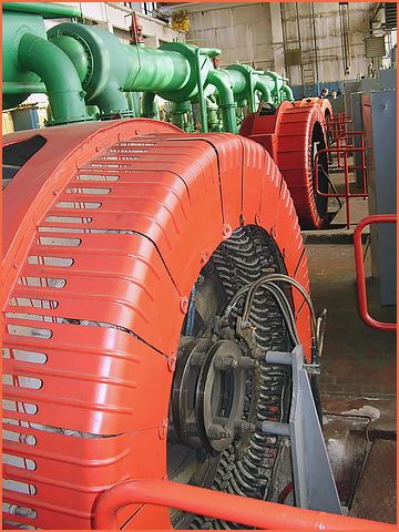
A century later, synchronous AC motors still represent one of most widely used technologies. Simply put, a synchronous motor is a rotary motor in which the speed of the rotating part or shaft is in synchrony or spins in tandem with the line frequency oscillations of the supply current (typically 60 Hz in the US and 50 Hz in Europe and Asia). To accomplish this, synchronous motors contain electromagnets usually on the rotor and a winding of a coil of copper wire (aka the field coil) around the stator ring. A small space, or air gap, separates the stator from the rotor, allowing the rotor to spin freely when the supply current is turned on. Depending on design requirements, the location of the electromagnets or field coil are interchangeably mountable on the stator or the rotor. When excited, electromagnets and the field coil work together to create a magnetic field that rotates in time with the oscillations of the line current. The rotor locks in, or turns in step, with this field at the same rate causing the shaft to rotate quickly. Once this occurs, the motor reaches steady-state operation and is in synchrony or “in sync”. If the motor load increases beyond breakdown load, the motor falls out of sync, and the field winding no longer follows the rotating magnetic field.
Synchronous motors are available in low and high horsepower industrial sizes. In low-voltage applications, synchronous motors are in use where precise constant speed is required. Small synchronous motors are able to start without assistance if the moment of inertia of the rotor and its mechanical load is sufficiently small. Small synchronous motors are commonly used in line-powered electric clocks and appliance timers.
After replacing the pump motor controller for the second time, we decided to find out what caused the controller to burn up. After operating for several days, we noticed excessive motor current on the controller. While we had the pump down for inspection, the customer technician removed and cleaned the filter screen. To continue our test we started the pump and the motor current was back to normal. What we learned was as the clogged filter screen increased the back pressure on the pump. To maintain the correct flow (pump speed) caused an increase in motor current to overcome the increased backpressure from the clogged filter screen. The motor current feedback was not included in the system diagnostics and the operators had not indication of the impending failure. The systems integrator undertook two improvement actions. (1) Increase the frequency at which all filter screens received cleaning and maintenance and (2) Brought the motor current value into an alarm to warn (predictive) the operators when a drive controller motor current was approaching and unsafe value. Why did the system integrator perform this work? Driven by the customer, the contract was written to require the system integrator to support the system for a pre-determined period of time after the system acceptance test.
 Servo Motor & Drives
Category
Featured
 Assuming that you checked the mechanical properties and the centrifugal force at the rotor at the higher speed from 50Hz to 60Hz, and they are OK, then ...
The troubleshooting guide outlines a comprehensive variety of motor problems. Generally the categories are arranged according to symptoms offering brief ...
The main difference between AC and DC motors is that the magnetic field generated by the stator rotates in the case of AC motors. A rotating magnetic ...
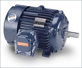 First, 7 things to consider when choosing an electric motor: Choosing the right motor isn’t always straightforward. There are so many variables to ...
Induction motors operate on the principal of current induction in the rotor which must rotate at a speed less than synchronous speed for induction to ...
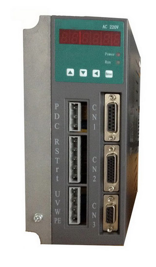 Gozuk synchronous ac servo drive is designed and manufactured, employing the advanced control algorithm based on the market demand, which can realize ...
A BLDC motor may have a trapezoidal Back EMF, there is something called Trapezoidal Motor Control Methodalogy (TRZ). TRZ is an extension of 6-step control ...
Permanent Magnet motors are more efficient than SCIM as the field in the rotor is permanently there. The big advantage for permanent magnet motors is in ...
