Motor testing
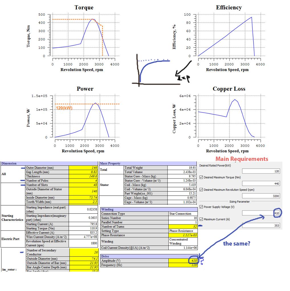
I'm in a motor design. Currently, I'm using JMAG Express to estimate the right sizing requirements for a 3-phase Induction Motor that I want to build among friends. As you can see from the picture, I need to be able to reach 3200 RPMs speed, 440 N*m torque and 120kW of max power. I've played around with some of the values in JMAG to reach a weight of around 20kg as you can see from the picture. The low weight is a very important requirement for the project and it should not exceed 50kg. I'm using 48 slots for the stator and 26 for the rotor which is a Caged type. Winding is concentrated with 32 turns.


Motor Failed…Who Cares?
Too often we hear maintenance & reliability experts downplay the data analysis or testing of motors that have failed from a stator fault. "Why would you need test equipment to test a stator fault?" we might hear. The mistake these "experts" make is to assume that troubleshooting a motor begins with failure analysis. Smart motors are on the market, but we haven't seen any with a big red flag that pops up with the words "STATOR FAULT" when it trips or fails to start. The reality most non-clairvoyant technicians face is they don't know exactly what failed, or if anything failed at all. Is it the motor, the load, the starter or maybe a nuisance trip? Remember a very important role of your predictive technologies is to assist the technicians in a quick recovery effort of production in the unfortunate situation of an unplanned outage. Performing some quick tests such as phase resistance, phase inductance, and ground wall tests can allow the technician to isolate quickly focus on or off of the electric motor and hasten good decision-making in deciding if a repair or replacement is necessary. A simple phase imbalance test may just prevent you from replacing a motor that doesn't need to be replaced.
It's Not Always the Motor's Fault
When testing a motor it is good practice to thoroughly test the entire motor circuit. A Wound Rotor Motor has two circuits – the stator circuit, which is very similar to a standard AC induction motor, and a rotor circuit. The rotor circuit usually consists of rotor windings, rings and brushes, and a resistor bank controlled using contactors. Depending on the application, the rotor circuit is used to control the torque, speed, or startup current of the motor. The external portion of the rotor circuit usually consists of an external resistor bank with a number of resistance steps. An unbalance of resistance in the resistor bank will cause an unbalance of the flux in the rotor creating a situation similar to a broken rotor bar. There are several tests using the MCEMAX that can be performed to evaluate this situation. With the motor de-energized, a standard test can be performed on each step of the resistor bank circuit to ensure resistance is balanced through each step and when the resistor bank is fully shorted out. With the motor running, a rotor evaluation test can be performed to look for a current unbalance during startup and after the motor is at full speed. An In-Rush test can be used to evaluate startup and switching times when troubleshooting anomalies in the rotor circuit.
I'd be very careful about surge testing motors in industrial environments. There is specific guidance from IEEE, NEMA and EASA that talks about surge testing being potentially destructive when done on motors in the field. More specifically, motors with unknown insulation conditions. Surge and hi pot testing are geared for shop testing on repaired or new motors. I'd recommend monitoring online impedance imbalance and current imbalance. We've seen many case studies where these two parameters were early indicators of stator faults. I agree that offline, phase to phase resistance and inductance can be great indicators of stator faults. The downside of offline testing is the fact the motor has to be shutdown.
We also recommend looking for faults conducive to stator failures. For example, if you have a high restive imbalance on the circuit this can increase heat inside the motor. The increased heat further stresses the insulation system and can lead to bigger insulation or stator failures. If we could have found the small problem, ie. resistance imbalance, then we could have prevented the stator fault.
Stator is a tricky fault zone because faults typically develop so quickly. With a good overall motor testing program you can find the faults that lead to stator issues and get them corrected early.
I was trying to point out that impedance imbalance and current imbalance can act as good indicators for stator issues. It seemed to me that most people in the discussion we're focusing on offline tests and there wasn't much mention of online stator testing.
I did some analysis on an induction motor some years ago re speed or torque control at low speed without a sensor. I concluded that there was nothing to sense and that it could not be done. In the last twenty years I have seen some improvement in sensorless control, but have not seen anyone do it at zero speed. I build motion bases using induction motors as servo motors, and I do get full torque at stall with a V/f drive using a feedback pot for position control.
 Servo Motor & Drives
Category
Featured
 Assuming that you checked the mechanical properties and the centrifugal force at the rotor at the higher speed from 50Hz to 60Hz, and they are OK, then ...
The troubleshooting guide outlines a comprehensive variety of motor problems. Generally the categories are arranged according to symptoms offering brief ...
The main difference between AC and DC motors is that the magnetic field generated by the stator rotates in the case of AC motors. A rotating magnetic ...
 First, 7 things to consider when choosing an electric motor: Choosing the right motor isn’t always straightforward. There are so many variables to ...
Induction motors operate on the principal of current induction in the rotor which must rotate at a speed less than synchronous speed for induction to ...
 Gozuk synchronous ac servo drive is designed and manufactured, employing the advanced control algorithm based on the market demand, which can realize ...
A BLDC motor may have a trapezoidal Back EMF, there is something called Trapezoidal Motor Control Methodalogy (TRZ). TRZ is an extension of 6-step control ...
Permanent Magnet motors are more efficient than SCIM as the field in the rotor is permanently there. The big advantage for permanent magnet motors is in ...
