How much is the inductance of the "empty" motor?
About the "empty" induction motor, as an R-L load, I wanted to do the same (recently it was for testing dead-time compensation, since the motion induced back-EMF would have added some "noise" to my measurements), but I expected the inductance to be orders of magnitude lower than with the rotor, how much is the inductance of the "empty" motor (roughly), and the rating of the original motor?
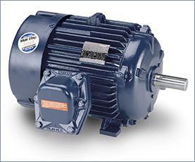
I used a NEMA-design induction motor, which have fairly high inductance so they can be line-started. I don't recall the inductances, but I made sure to use a motor with a similar power rating to the variable frequency drive.
Don't worry about the inductance without the rotor. If you work through the equations you'll find that the stator R-L time constant dominates the current ripple at the switching frequency. Not enough flux crosses the air-gap at the switching frequency to make much difference.
The rotor does modify the inductance. You will have to be a little careful about how much voltage you apply to the phases, because you can easily generate too much current (a given, since there's no back-emf, either). But at the switching frequency, very little flux crosses the airgap so the rotor does not really figure into the equations for DC bus ripple current. And in this sort of testing, it's DC bus ripple that can accidentally destroy the variable frequency drive you are trying to verify!
<- - Make a Comment - ->

 Servo Motor & Drives

